Thursday, 30 October 2014

Union Transformation in Informatica

Union transformation is an active and connected transformation. It is multi input group transformation used to merge the data from multiple pipelines into a single pipeline. Basically it merges data from multiples sources just like the UNION ALL set operator in SQL. The union transformation does not remove any duplicate rows.
Union Transformation Guidelines
The following rules and guidelines should be used when using a union transformation in a mapping
  • Union transformation contains only one output group and can have multiple input groups.
  • The input groups and output groups should have matching ports. The datatype, precision and scale must be same.
  • Union transformation does not remove duplicates. To remove the duplicate rows use sorter transformation with "select distinct" option after the union transformation.
  • The union transformation does not generate transactions.
  • You cannot connect a sequence generator transformation to the union transformation.
  • Union transformation does not generate transactions.
Creating union transformation
Follow the below steps to create a union transformation
  1. Go the mapping designer, create a new mapping or open an existing mapping
  2. Go to the toolbar-> click on Transformations->Create
  3. Select the union transformation and enter the name. Now click on Done and then click on OK.
  4. Go to the Groups Tab and then add a group for each source you want to merge.
  5. Go to the Group Ports Tab and add the ports.
Components of union transformation
Configure the following tabs of union transformation
  • Transformation: You can enter name and description of the transformation
  • Properties: Specify the amount of tracing level to be tracked in the session log.
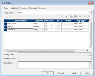
  • Groups Tab: You can create new input groups or delete existing input groups.
  • Group Ports Tab: You can create and delete ports for the input groups.
Note: The ports tab displays the groups and ports you create. You cannot edit the port or group information in the ports tab. To do changes use the groups tab and group ports tab.
Why union transformation is active
Union is an active transformation because it combines two or more data streams into one. Though the total number of rows passing into the Union is the same as the total number of rows passing out of it, and the sequence of rows from any given input stream is preserved in the output, the positions of the rows are not preserved, i.e. row number 1 from input stream 1 might not be row number 1 in the output stream. Union does not even guarantee that the output is repeatable.
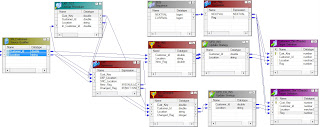
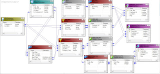
Union Transformation Example
1. There are two tables in the source. The table names are employees_US and employees_UK and have the structure. Create a mapping to load the data of these two tables into single target table employees?


Transaction Control Transformation in Informatica

Transaction Control is an active and connected transformation. The transaction control transformation is used to control the commit and rollback of transactions. You can define a transaction based on varying number of input rows. As an example, you can define a transaction on a group rows in the employees data using the department Id as a key.
In the informatica power center, you can define the transaction at the following levels:
  • Mapping level: Use the transaction control transformation to define the transactions.
  • Session level: You can specify the "Commit Type" option in the session properties tab. The different options of "Commit Type" are Target, Source and User Defined. If you have used the transaction control transformation in the mapping, then the "Commit Type" will always be "User Defined"
When you run a session, the integration service evaluates the expression for each row in the transaction control transformation. When it evaluates the expression as commit, then it commits all the rows in the transaction to the target(s). When the integration service evaluates the expression as rollback, then it roll back all the rows in the transaction from the target(s).
When you have flat file as the target, then the integration service creates an output file for each time it commits the transaction. You can dynamically name the target flat files. Look at the example for creating flat files dynamically - Dynamic flat file creation.
Creating Transaction Control Transformation
Follow the below steps to create transaction control transformation:
  • Go to the mapping designer, click on transformation in the toolbar, Create.
  • Select the transaction control transformation, enter the name and click on Create and then Done.
  • You can drag the ports in to the transaction control transformation or you can create the ports manually in the ports tab.
  • Go to the properties tab. Enter the transaction control expression in the Transaction Control Condition.
Configuring Transaction Control Transformation
You can configure the following components in the transaction control transformation:
  • Transformation Tab: You can rename the transformation and add a description.
  • Ports Tab: You can create input/output ports
  • Properties Tab: You can define the transaction control expression and tracing level.
  • Metadata Extensions Tab: You can add metadata information.
Transaction Control Expression
You can enter the transaction control expression in the Transaction Control Condition option in the properties tab. The transaction control expression uses the IIF function to test each row against the condition. Use the following syntax for the expression
Syntax: 
IIF (condition, value1, value2)

Example: 
IIF(dept_id=10, TC_COMMIT_BEFORE,TC_ROLLBACK_BEFORE)
Use the following built-in variables in the expression editor of the transaction control transformation:
  • TC_CONTINUE_TRANSACTION: The Integration Service does not perform any transaction change for this row. This is the default value of the expression.
  • TC_COMMIT_BEFORE: The Integration Service commits the transaction, begins a new transaction, and writes the current row to the target. The current row is in the new transaction.
  • TC_COMMIT_AFTER: The Integration Service writes the current row to the target, commits the transaction, and begins a new transaction. The current row is in the committed transaction.
  • TC_ROLLBACK_BEFORE: The Integration Service rolls back the current transaction, begins a new transaction, and writes the current row to the target. The current row is in the new transaction.
  • TC_ROLLBACK_AFTER: The Integration Service writes the current row to the target, rolls back the transaction, and begins a new transaction. The current row is in the rolled back transaction.
If the transaction control transformation evaluates to a value other than the commit, rollback or continue, then the integration service fails the session.
Transaction Control Transformation in Mapping
Transaction control transformation defines or redefines the transaction boundaries in a mapping. It creates a new transaction boundary or drops any incoming transaction boundary coming from upstream active source or transaction control transformation.
Transaction control transformation can be effective or ineffective for the downstream transformations and targets in the mapping. The transaction control transformation can become ineffective for downstream transformations or targets if you have used transformation that drops the incoming transaction boundaries after it. The following transformations drop the transaction boundaries.
  • Aggregator transformation with Transformation scope as "All Input".
  • Joiner transformation with Transformation scope as "All Input".
  • Rank transformation with Transformation scope as "All Input".
  • Sorter transformation with Transformation scope as "All Input".
  • Custom transformation with Transformation scope as "All Input".
  • Custom transformation configured to generate transactions
  • Transaction Control transformation
  • A multiple input group transformation, such as a Custom transformation, connected to multiple upstream transaction control points.
Mapping Guidelines and Validation
Use the following rules and guidelines when you create a mapping with a Transaction Control transformation:
  • If the mapping includes an XML target, and you choose to append or create a new document on commit, the input groups must receive data from the same transaction control point.
  • Transaction Control transformations connected to any target other than relational, XML, or dynamic MQSeries targets are ineffective for those targets.
  • You must connect each target instance to a Transaction Control transformation.
  • You can connect multiple targets to a single Transaction Control transformation.
  • You can connect only one effective Transaction Control transformation to a target.
  • You cannot place a Transaction Control transformation in a pipeline branch that starts with a Sequence Generator transformation.
  • If you use a dynamic Lookup transformation and a Transaction Control transformation in the same mapping, a rolled-back transaction might result in unsynchronized target data.
  • A Transaction Control transformation may be effective for one target and ineffective for another target. If each target is connected to an effective Transaction Control transformation, the mapping is valid.
  • Either all targets or none of the targets in the mapping should be connected to an effective Transaction Control transformation.

Case Converter Transformation in informatica

The Case converter transformation is a passive transformation used to format the data to similar character formats. Case converter transformation is used to maintain data quality.
The predefined case conversion types are uppercase, lowercase, toggle case, title case and sentence case.
Reference tables can also be used to control the case conversion. Use the "Valid" column in the reference table to change the case of input strings. Use reference tables only when the case conversion type is "title case or sentence case".

Case Strategy Properties:

You can create multiple case conversion strategies. Each strategy uses a single conversion type. Configure the following properties on the strategies view in the case converter transformation:

Reference Tables: used to apply the capitalization format specified by a reference table. Reference tables work only if the case conversion option is title case or sentence case. If a reference table match occurs at the start of a string, the next character in that string changes to uppercase. For example, if the input string is vieditor and the reference table has an entry for Vi, the output string is ViEditor.

Conversion Types: The conversion types are uppercase, lowercase, toggle case, title case and sentence case. The default conversion type is uppercase.

Leave uppercase words unchanged: Overrides the chosen capitalization for uppercase strings.
Delimiters: Specifies how capitalization functions work for title case conversion. For example, choose a colon as a delimiter to transform "james:bond" to "James:Bond". The default delimiter is the space character.

For more Visit  http://www.quontrasolutions.com/blog/category/informatica/

Create/Implement SCD - Informatica Mapping Wizard

Q) How to create different types of slowly changing dimensions (SCD) in informatica using the mapping wizard?
The Mapping Wizards in informatica provides an easy way to create the different types of SCDs. We will see how to create the SCDs using the mapping wizards in step by step.
The below steps are common for creating the SCD type 1, type 2 and type 3
Open the mapping designer tool, Go to the source analyzer tab and either create or import the source definition. As an example i am using the customer table as the source. The fields in the customer table are listed below.
Customers (Customer_Id, Customer_Name, Location)
Go to the mapping designer tab, in the tool bar click on Mappings, select Wizards and then click on Slowly Changing Dimensions.
Now enter the mapping name and select the SCD mapping type you want to create. This is shown in the below image. Then click on Next.
Select the source table name (Customers in this example) and enter the name for the target table to be created. Then click on next.
Now you have to select the logical key fields and fields to compare for changes. Logical key fields are the fields which the source qualifier and the Lookup will be joined. Fields to compare for changes are the fields which are used to determine whether the values are changed or not. Here i am using customer_id as the logical key field and the location as the field to compare.
As of now we have seen the common steps for creating the SCDs. Now we will see the specific steps for creating each SCD
SCD Type 1 Mapping:
Once you have selected the logical key fields and fields to compare for changes. Then you have to simply click the finish button to create the SCD Type 1 mapping.
SCD Type 2 Mapping:
After selecting the logical fields click on the next button. You will get a window where you can select what type of SCD 2 you want to create. For
  • Versioning: select "keep the version number in separate column"
  • Flagging: select "Mark the current dimension record with a flag"
  • Effective Date: select "Mark the dimension records with their effective date.
Once you have selected the required type, then click on the finish button to create the SCD type 2 mapping.
SCD Type 3 Mapping:
Click on the next button after selecting the logical key fields. You will get window for selecting the optional Effective Date. If you want the effective date to be created in the dimension table, you can check this box or else ignore. Now click on the finish button to create the SCD type 3 mapping.

Design/Implement/Create SCD Type 2 Version Mapping in Informatica

Q) How to create or implement slowly changing dimension (SCD) Type 2 versioning mapping in informatica?
SCD type 2 will store the entire history in the dimension table.
We will see how to implement the SCD Type 2 version in informatica. As an example consider the customer dimension. The source and target table structures are shown below:
--Source Table

Create Table Customers
(
  Customer_Id Number Primary Key,
  Location    Varchar2(30)
);

--Target Dimension Table

Create Table Customers_Dim
(
  Cust_Key Number Primary Key,
  Customer_Id   Number,
  Location      Varchar2(30),
  Version       Number
);
The basic steps involved in creating a SCD Type 2 version mapping are
  • Identifying the new records and inserting into the dimension table with version number as one.
  • Identifying the changed record and inserting into the dimension table by incrementing the version number.
Lets divide the steps to implement the SCD type 2 version mapping into three parts.
SCD Type 2 version implementation - Part 1
Here we will see the basic set up and mapping flow require for SCD type 2 version. The steps involved are:
  • Create the source and dimension tables in the database.
  • Open the mapping designer tool, source analyzer and either create or import the source definition.
  • Go to the Warehouse designer or Target designer and import the target definition.
  • Go to the mapping designer tab and create new mapping.
  • Drag the source into the mapping.
  • Go to the toolbar, Transformation and then Create.
  • Select the lookup Transformation, enter a name and click on create. You will get a window as shown in the below image.


  • Select the customer dimension table and click on OK.
  • Edit the lookup transformation, go to the ports tab and remove unnecessary ports. Just keep only Cust_key, customer_id, location ports and Version ports in the lookup transformation. Create a new port (IN_Customer_Id) in the lookup transformation. This new port needs to be connected to the customer_id port of the source qualifier transformation.


  • Go to the conditions tab of the lookup transformation and enter the condition as Customer_Id = IN_Customer_Id
  • Go to the properties tab of the LKP transformation and enter the below query in Lookup SQL Override. Alternatively you can generate the SQL query by connecting the database in the Lookup SQL Override expression editor and then add the order by clause.

SELECT  Customers_Dim.Cust_Key as Cust_Key,
        Customers_Dim.Location as Location,
        Customers_Dim.Version as Version,
        Customers_Dim.Customer_Id as Customer_Id
FROM    Customers_Dim
ORDER BY  Customers_Dim.Customer_Id, Customers_Dim.Version--

  • You have to use an order by clause in the above query. If you sort the version column in ascending order, then you have to specify "Use Last Value" in the "Lookup policy on multiple match" property. If you have sorted the version column in descending order then you have to specify the "Lookup policy on multiple match" option as "Use First Value"
  • Click on Ok in the lookup transformation. Connect the customer_id port of source qualifier transformation to the In_Customer_Id port of the LKP transformation.
  • Create an expression transformation with input/output ports as Cust_Key, LKP_Location, Src_Location and output ports as New_Flag, Changed_Flag. Enter the below expressions for output ports.

New_Flag = IIF(ISNULL(Cust_Key), 1,0)
Changed_Flag = IIF( NOT ISNULL(Cust_Key) AND
               LKP_Location != SRC_Location, 1, 0)
The part of the mapping flow is shown below.
SCD Type 2 version implementation - Part 2
In this part, we will identify the new records and insert them into the target with version value as 1. The steps involved are:
  • Now create a filter transformation to identify and insert new record in to the dimension table. Drag the ports of expression transformation (New_Flag) and source qualifier transformation (Customer_Id, Location) into the filter transformation.
  • Go the properties tab of filter transformation and enter the filter condition as New_Flag=1
  • Now create a update strategy transformation and connect the ports of filter transformation (Customer_Id, Location). Go to the properties tab and enter the update strategy expression as DD_INSERT.
  • Now drag the target definition into the mapping and connect the appropriate ports of update strategy transformation to the target definition.
  • Create a sequence generator and an expression transformation. Call this expression transformation as "Expr_Ver".
  • Drag and connect the NextVal port of sequence generator to the Expression transformation. In the expression transformation create a new output port (Version) and assign value 1 to it.
  • Now connect the ports of expression transformation (Nextval, Version) to the Target definition ports (Cust_Key, Version). The part of the mapping flow is shown in the below image.

SCD Type 2 Version implementation - Part 3
In this part, we will identify the changed records and insert them into the target by incrementing the version number. The steps involved are:
  • Create a filter transformation. This is used to find the changed record. Now drag the ports from expression transformation (changed_flag), source qualifier transforamtion (customer_id, location) and LKP transformation (version) into the filter transformation.
  • Go to the filter transformation properties and enter the filter condition as changed_flag =1.
  • Create an expression transformation and drag the ports of filter transformation except the changed_flag port into the expression transformation.
  • Go to the ports tab of expression transformation and create a new output port (O_Version) and assign the expression as (version+1).
  • Now create an update strategy transformation and drag the ports of expression transformation (customer_id, location,o_version) into the update strategy transformation. Go to the properties tab and enter the update strategy expression as DD_INSERT.
  • Now drag the target definition into the mapping and connect the appropriate ports of update strategy transformation to the target definition.
  • Now connect the Next_Val port of expression transformation (Expr_Ver created in part 2) to the cust_key port of the target definition. The complete mapping diagram is shown in the below image:

You can implement the SCD type 2 version mapping in your own way. Remember that SCD type2 version mapping is rarely used in real time.

For more Visit  http://www.quontrasolutions.com/blog/category/informatica/

Design/Implement/Create SCD Type 2 Flag Mapping in Informatica

Q) How to create or implement slowly changing dimension (SCD) Type 2 Flagging mapping in informatica?
SCD type 2 will store the entire history in the dimension table.
We will see how to implement the SCD Type 2 Flag in informatica. As an example consider the customer dimension. The source and target table structures are shown below:
--Source Table

Create Table Customers
(
  Customer_Id Number Primary Key,
  Location    Varchar2(30)
);

--Target Dimension Table

Create Table Customers_Dim
(
  Cust_Key Number Primary Key,
  Customer_Id   Number,
  Location      Varchar2(30),
  Flag       Number
);
The basic steps involved in creating a SCD Type 2 Flagging mapping are
  • Identifying the new records and inserting into the dimension table with flag column value as one.
  • Identifying the changed record and inserting into the dimension table with flag value as one.
  • Identify the changed record and update the existing record in dimension table with flag value as zero.
We will divide the steps to implement the SCD type 2 flagging mapping into four parts.
SCD Type 2 Flag implementation - Part 1
Here we will see the basic set up and mapping flow require for SCD type 2 Flagging. The steps involved are:
  • Create the source and dimension tables in the database.
  • Open the mapping designer tool, source analyzer and either create or import the source definition.
  • Go to the Warehouse designer or Target designer and import the target definition.
  • Go to the mapping designer tab and create new mapping.
  • Drag the source into the mapping.
  • Go to the toolbar, Transformation and then Create.
  • Select the lookup Transformation, enter a name and click on create. You will get a window as shown in the below image.
  • Select the customer dimension table and click on OK.
  • Edit the lookup transformation, go to the ports tab and remove unnecessary ports. Just keep only Cust_key, customer_id and location ports in the lookup transformation. Create a new port (IN_Customer_Id) in the lookup transformation. This new port needs to be connected to the customer_id port of the source qualifier transformation.
  • Go to the conditions tab of the lookup transformation and enter the condition as Customer_Id = IN_Customer_Id
  • Go to the properties tab of the LKP transformation and enter the below query in Lookup SQL Override. Alternatively you can generate the SQL query by connecting the database in the Lookup SQL Override expression editor and then add the WHERE clause.
SELECT  Customers_Dim.Cust_Key as Cust_Key,
        Customers_Dim.Location as Location,
        Customers_Dim.Customer_Id as Customer_Id
FROM    Customers_Dim
WHERE   Customers_Dim.Flag = 1
  • Click on Ok in the lookup transformation. Connect the customer_id port of source qualifier transformation to the In_Customer_Id port of the LKP transformation.
  • Create an expression transformation with input/output ports as Cust_Key, LKP_Location, Src_Location and output ports as New_Flag, Changed_Flag. Enter the below expressions for output ports.
New_Flag = IIF(ISNULL(Cust_Key), 1,0)
Changed_Flag = IIF( NOT ISNULL(Cust_Key) AND
               LKP_Location != SRC_Location, 1, 0)
  • The part of the mapping flow is shown below.
SCD Type 2 Flag implementation - Part 2
In this part, we will identify the new records and insert them into the target with flag value as 1. The steps involved are:
  • Now create a filter transformation to identify and insert new record in to the dimension table. Drag the ports of expression transformation (New_Flag) and source qualifier transformation (Customer_Id, Location) into the filter transformation.
  • Go the properties tab of filter transformation and enter the filter condition as New_Flag=1
  • Now create a update strategy transformation and connect the ports of filter transformation (Customer_Id, Location). Go to the properties tab and enter the update strategy expression as DD_INSERT.
  • Now drag the target definition into the mapping and connect the appropriate ports of update strategy transformation to the target definition.
  • Create a sequence generator and an expression transformation. Call this expression transformation as "Expr_Flag".
  • Drag and connect the NextVal port of sequence generator to the Expression transformation. In the expression transformation create a new output port (Flag) and assign value 1 to it.
  • Now connect the ports of expression transformation (Nextval, Flag) to the Target definition ports (Cust_Key, Flag). The part of the mapping flow is shown in the below image.
SCD Type 2 Flag implementation - Part 3
In this part, we will identify the changed records and insert them into the target with flag value as 1. The steps involved are:
  • Create a filter transformation. Call this filter transformation as FIL_Changed. This is used to find the changed records. Now drag the ports from expression transformation (changed_flag), source qualifier transformation (customer_id, location), LKP transformation (Cust_Key) into the filter transformation.
  • Go to the filter transformation properties and enter the filter condition as changed_flag =1.
  • Now create an update strategy transformation and drag the ports of Filter transformation (customer_id, location) into the update strategy transformation. Go to the properties tab and enter the update strategy expression as DD_INSERT.
  • Now drag the target definition into the mapping and connect the appropriate ports of update strategy transformation to the target definition.
  • Now connect the Next_Val, Flag ports of expression transformation (Expr_Flag created in part 2) to the cust_key, Flag ports of the target definition respectively. The part of the mapping diagram is shown below.
SCD Type 2 Flag implementation - Part 4
In this part, we will update the changed records in the dimension table with flag value as 0.
  • Create an expression transformation and drag the Cust_Key port of filter transformation (FIL_Changed created in part 3) into the expression transformation.
  • Go to the ports tab of expression transformation and create a new output port (Flag). Assign a value "0" to this Flag port.
  • Now create an update strategy transformation and drag the ports of the expression transformation into it. Go to the properties tab and enter the update strategy expression as DD_UPDATE.
  • Drag the target definition into the mapping and connect the appropriate ports of update strategy to it. The complete mapping image is shown below.

Design/Implement/Create SCD Type 2 Effective Date Mapping in Informatica

Q) How to create or implement slowly changing dimension (SCD) Type 2 Effective Date mapping in informatica?
SCD type 2 will store the entire history in the dimension table. In SCD type 2 effective date, the dimension table will have Start_Date (Begin_Date) and End_Date as the fields. If the End_Date is Null, then it indicates the current row.
We will see how to implement the SCD Type 2 Effective Date in informatica. As an example consider the customer dimension. The source and target table structures are shown below:
--Source Table

Create Table Customers
(
  Customer_Id Number Primary Key,
  Location    Varchar2(30)
);

--Target Dimension Table

Create Table Customers_Dim
(
  Cust_Key Number Primary Key,
  Customer_Id   Number,
  Location      Varchar2(30),
  Begin_Date    Date,
  End_Date      Date
);
The basic steps involved in creating a SCD Type 2 Effective Date mapping are
  • Identifying the new records and inserting into the dimension table with Begin_Date as the Current date (SYSDATE) and End_Date as NULL.
  • Identifying the changed record and inserting into the dimension table with Begin_Date as the Current date (SYSDATE) and End_Date as NULL.
  • Identify the changed record and update the existing record in dimension table with End_Date as Curren date.
We will divide the steps to implement the SCD type 2 Effective Date mapping into four parts.
SCD Type 2 Effective Date implementation - Part 1
Here we will see the basic set up and mapping flow require for SCD type 2 Effective Date. The steps involved are:
  • Create the source and dimension tables in the database.
  • Open the mapping designer tool, source analyzer and either create or import the source definition.
  • Go to the Warehouse designer or Target designer and import the target definition.
  • Go to the mapping designer tab and create new mapping.
  • Drag the source into the mapping.
  • Go to the toolbar, Transformation and then Create.
  • Select the lookup Transformation, enter a name and click on create. You will get a window as shown in the below image.
  • Select the customer dimension table and click on OK.
  • Edit the lookup transformation, go to the ports tab and remove unnecessary ports. Just keep only Cust_key, customer_id and location ports in the lookup transformation. Create a new port (IN_Customer_Id) in the lookup transformation. This new port needs to be connected to the customer_id port of the source qualifier transformation.
  • Go to the conditions tab of the lookup transformation and enter the condition as Customer_Id = IN_Customer_Id
  • Go to the properties tab of the LKP transformation and enter the below query in Lookup SQL Override. Alternatively you can generate the SQL query by connecting the database in the Lookup SQL Override expression editor and then add the WHERE clause.
SELECT  Customers_Dim.Cust_Key as Cust_Key,
        Customers_Dim.Location as Location,
        Customers_Dim.Customer_Id as Customer_Id
FROM    Customers_Dim
WHERE   Customers_Dim.End_Date IS NULL
  • Click on Ok in the lookup transformation. Connect the customer_id port of source qualifier transformation to the In_Customer_Id port of the LKP transformation.
  • Create an expression transformation with input/output ports as Cust_Key, LKP_Location, Src_Location and output ports as New_Flag, Changed_Flag. Enter the below expressions for output ports.
New_Flag = IIF(ISNULL(Cust_Key), 1,0)
Changed_Flag = IIF( NOT ISNULL(Cust_Key) AND
               LKP_Location != SRC_Location, 1, 0)
  • The part of the mapping flow is shown below.
SCD Type 2 Effective Date implementation - Part 2
In this part, we will identify the new records and insert them into the target with Begin Date as the current date. The steps involved are:
  • Now create a filter transformation to identify and insert new record in to the dimension table. Drag the ports of expression transformation (New_Flag) and source qualifier transformation (Customer_Id, Location) into the filter transformation.
  • Go the properties tab of filter transformation and enter the filter condition as New_Flag=1
  • Now create a update strategy transformation and connect the ports of filter transformation (Customer_Id, Location). Go to the properties tab and enter the update strategy expression as DD_INSERT.
  • Now drag the target definition into the mapping and connect the appropriate ports of update strategy transformation to the target definition.
  • Create a sequence generator and an expression transformation. Call this expression transformation as "Expr_Date".
  • Drag and connect the NextVal port of sequence generator to the Expression transformation. In the expression transformation create a new output port (Begin_Date with date/time data type) and assign value SYSDATE to it.
  • Now connect the ports of expression transformation (Nextval, Begin_Date) to the Target definition ports (Cust_Key, Begin_Date). The part of the mapping flow is shown in the below image.
SCD Type 2 Effective Date implementation - Part 3
In this part, we will identify the changed records and insert them into the target with Begin Date as the current date. The steps involved are:
  • Create a filter transformation. Call this filter transformation as FIL_Changed. This is used to find the changed records. Now drag the ports from expression transformation (changed_flag), source qualifier transformation (customer_id, location), LKP transformation (Cust_Key) into the filter transformation.
  • Go to the filter transformation properties and enter the filter condition as changed_flag =1.
  • Now create an update strategy transformation and drag the ports of Filter transformation (customer_id, location) into the update strategy transformation. Go to the properties tab and enter the update strategy expression as DD_INSERT.
  • Now drag the target definition into the mapping and connect the appropriate ports of update strategy transformation to the target definition.
  • Now connect the Next_Val, Begin_Date ports of expression transformation (Expr_Date created in part 2) to the cust_key, Begin_Date ports of the target definition respectively. The part of the mapping diagram is shown below.
SCD Type 2 Effective Date implementation - Part 4
In this part, we will update the changed records in the dimension table with End Date as current date.
  • Create an expression transformation and drag the Cust_Key port of filter transformation (FIL_Changed created in part 3) into the expression transformation.
  • Go to the ports tab of expression transformation and create a new output port (End_Date with date/time data type). Assign a value SYSDATE to this port.
  • Now create an update strategy transformation and drag the ports of the expression transformation into it. Go to the properties tab and enter the update strategy expression as DD_UPDATE.
  • Drag the target definition into the mapping and connect the appropriate ports of update strategy to it. The complete mapping image is shown below.

Create/Design/Implement SCD Type 3 Mapping in Informatica

Q) How to create or implement or design a slowly changing dimension (SCD) Type 3 using the informatica ETL tool.
The SCD Type 3 method is used to store partial historical data in the Dimension table. The dimension table contains the current and previous data.
The process involved in the implementation of SCD Type 3 in informatica is
  • Identifying the new record and insert it in to the dimension table.
  • Identifying the changed record and update the existing record in the dimension table.
We will see the implementation of SCD type 3 by using the customer dimension table as an example. The source table looks as
CREATE TABLE Customers (
  Customer_Id   Number,
  Location      Varchar2(30)
)
Now I have to load the data of the source into the customer dimension table using SCD Type 3. The Dimension table structure is shown below.
CREATE TABLE Customers_Dim (
  Cust_Key      Number,
  Customer_Id   Number,
  Curent_Location      Varchar2(30),
  Previous_Location      Varchar2(30)
)
Steps to Create SCD Type 3 Mapping
Follow the below steps to create SCD Type 3 mapping in informatica
  • Create the source and dimension tables in the database.
  • Open the mapping designer tool, source analyzer and either create or import the source definition.
  • Go to the Warehouse designer or Target designer and import the target definition.
  • Go to the mapping designer tab and create new mapping.
  • Drag the source into the mapping.
  • Go to the toolbar, Transformation and then Create.
  • Select the lookup Transformation, enter a name and click on create. You will get a window as shown in the below image.
  • Select the customer dimension table and click on OK.
  • Edit the LKP transformation, go to the properties tab, remove the Previous_Location port and add a new port In_Customer_Id. This new port needs to be connected to the Customer_Id port of source qualifier transformation.
  • Go to the condition tab of LKP transformation and enter the lookup condition as Customer_Id = IN_Customer_Id. Then click on OK.
  • Connect the customer_id port of source qualifier transformation to the IN_Customer_Id port of LKP transformation.
  • Create the expression transformation with input ports as Cust_Key, Prev_Location, Curr_Location and output ports as New_Flag, Changed_Flag
  • For the output ports of expression transformation enter the below expressions and click on ok
New_Flag = IIF(ISNULL(Cust_Key),1,0)
Changed_Flag = IIF(NOT ISNULL(Cust_Key)
                   AND Prev_Location != Curr_Location,
                   1, 0 )       
  • Now connect the ports of LKP transformation (Cust_Key, Curent_Location) to the expression transformaiton ports (Cust_Key, Prev_Location) and ports of source qualifier transformation (Location) to the expression transformation ports (Curr_Location) respectively.
  • The mapping diagram so far created is shown in the below image.
  • Create a filter transformation and drag the ports of source qualifier transformation into it. Also drag the New_Flag port from the expression transformation into it.
  • Edit the filter transformation, go to the properties tab and enter the Filter Condition as New_Flag=1. Then click on ok.
  • Now create an update strategy transformation and connect all the ports of the filter transformation (except the New_Flag port) to the update strategy. Go to the properties tab of update strategy and enter the update strategy expression as DD_INSERT
  • Now drag the target definition into the mapping and connect the appropriate ports from update strategy to the target definition. Connect Location port of update strategy to the Current_Location port of the target definition.
  • Create a sequence generator transformation and connect the NEXTVAL port to the target surrogate key (cust_key) port.
  • The part of the mapping diagram for inserting a new row is shown below:
  • Now create another filter transformation, Go to the ports tab and create the ports Cust_Key, Curr_Location, Prev_Location, Changed_Flag. Connect the ports LKP Transformation (Cust_Key, Current_Location) to the filter transformation ports (Cust_Key, Prev_Location), source qualifier transformation ports (Location) to the filter transformation port (Curr_Location) and expression transformation port(changed_flag) to the changed_flag port of the filter transformation.
  • Edit the filter transformation, go to the properties tab and enter the Filter Condition as Changed_Flag=1. Then click on ok.
  • Now create an update strategy transformation and connect the ports of the filter transformation (Cust_Key, Curr_Location, Prev_location) to the update strategy. Go to the properties tab of update strategy and enter the update strategy expression as DD_Update
  • Now drag the target definition into the mapping and connect the appropriate ports from update strategy to the target definition.
  • The complete mapping diagram is shown in the below image.

Parameterizing the Flat File Names - Informatica

Q) How to load the data from a flat file into the target where the source flat file name changes daily?
Example: I want to load the customers data into the target file on a daily basis. The source file name is in the format customers_yyyymmdd.dat. How to load the data where the filename varies daily?
The solution to this kind of problems is using the parameters. You can specify session parameters for both the source and target flat files. Then create a parameter file and assign the flat file names to the parameters.

Specifying Parameters for File Names:

The steps involved in parameterizing the file names are:
  • Creating the Parameter File
  • Specifying the parameters in Session
  • Specifying the parameter file name
Creating Parameter File:

Assume two session parameters $InputFileName and $OutputFileName for specifying the source and target flat file names respectively. Now create a parameter file in the below format
> cat dynamic_file_names.param
[FolderName.SessionName]

$InputFileName=customers_20120101.dat

$outputFileName=customers_file.dat
 
Specifying Parameters in Session:

Now you have to specify the parameters in the session. Edit the session and go to the Mapping tab. In the mapping tab, select the source qualifier in the Sources folder and set the file property "Source FileName" as $InputFileName. Similarly, for target file set the "Source FileName" as $OutputFileName.

Specifying Parameter File Name:

The last step is specifying the parameter file name. You can specify the parameter file name either in the session level or workflow level. To specify in the session level, go the properties tab of the session and set the property "Parameter FileName".
To specify the parameter file at workflow level, click on the "Worfklows" in toolbar and then on Edit. Now go to the properties and set the file property "Parameter FileName"
Thats it you are done with using the parameters as filenames. Now you have to take care of changing the file name in the parameter file daily.
Note: You can even specify the source and target directories as parameters.

For more Visit  http://www.quontrasolutions.com/blog/category/informatica/

TE_7073: Expecting Keys to be ascending - Informatica

Aggregator Transformation computes calculations on a group of rows and returns a single row for each group. We can improve the performance of aggregator transformation by sorting the data on the group by ports and then specifying the "Sorted Input" option in the aggregator transformation properties.
The aggregator transformation will throw the below error if you do not sort the data and specified the "Sorted Input" option in the properties of the aggregator transformation:
TE_7073: Expecting Keys to be ascending
This error is due to the data sorting issues in the mapping. This is quite obvious as the aggregator transformation expects the data to be in sorted order and however it gets the data in unsorted order. To avoid this error, simply follow the below steps:

Sort on Group By Ports:
Be sure to sort the data using a sorter transformation or source qualifier transformation before passing to the aggregator transformation.
The order of the ports is important while sorting the data. The order of the ports that you specify in the sorter transformation should be exactly same as the order of the ports specified in "Group By" ports of aggregator transformation. If the order of the ports does not match, then you will get this error.

Trim String Ports:
If you are using the string or varchar ports in the "Group By" of aggregator transformation, then remove the trailing, leading spaces in the expression transformation and then pass to sorter transformation to sort the data.

Avoid Transformations that Change Sorting Order:
Do not place transformations which change the sorting order before the aggregator transformation.

For more Visit  http://www.quontrasolutions.com/blog/category/informatica/

Generate Date / Time Dimension in Informatica

We use database procedures to generate the date dimension for data warehouse applications. Here i am going to show you how to generate the date dimension in informatica.
Let see how to generate list out all the days between two given dates using oracle sql query.
SELECT  to_date('01-JAN-2000','DD-MON-YYYY') + level-1 calendar_date
FROM    dual
connect by level <= 
        ( 
           to_date('31-DEC-2000','DD-MON-YYYY') - 
           to_date('01-JAN-2000','DD-MON-YYYY') + 1
        );

Output:

CALENDAR_DATE
-------------
1/1/2000
1/2/2000
1/3/2000
.
.
.
12/31/2000
Now we can apply date functions on the Calendar date field and can derive the rest of the columns required in a date dimension.
We will see how to get the list of days between two given dates in informatica. Follow the below steps for creating the mapping in informatica.
  • Create a source with two ports ( Start_Date and End_Date) in the source analyzer.
  • Create a new mapping in the mapping designer Drag the source definition into the mapping.
  • Create the java transformation in active mode.
  • Drag the ports of source qualifier transformation in to the java transformation.
  • Now edit the java transformation by double clicking on the title bar and go to the "Java Code" tab. Here you will again find sub tabs. Go to the "Import Package" tab and enter the below java code:
import java.text.DateFormat;
import java.text.ParseException;
import java.text.SimpleDateFormat;
import java.util.Date;
  • Not all these packages are required. However i included just in case if you want to apply any formatting on dates. Go to the "On Input Row" tab and enter the following java code:
int num_days = (int) ((End_Date - Start_Date) / (1000 * 60 * 60 * 24));
long Start_Seconds = Start_Date;

for (int i=1; i <= num_days ; i++)
{
 if (i == 1)
 {
 generateRow();
 }
 else
 {
 Start_Date = Start_Date + (1000 * 60 * 60 * 24);
 generateRow();
 }
}

Start_Date = Start_Date + (1000 * 60 * 60 * 24);
generateRow();
  • Compile the java code by clicking on the compile. This will generate the java class files.
  • Connect only the Start_Date output port from java transformation to expression transformation.
  • Connect the Start_Date port from expression transformation to target and save the mapping.
  • Now create a workflow and session. Enter the following oracle sql query in the Source SQL Query option:
SELECT to_date('01-JAN-2000','DD-MON-YYYY') Start_Date,
       to_date('31-DEC-2000','DD-MON-YYYY') End_Date
FROM   DUAL;
Save the workflow and run. Now in the target you can see the list of dates loaded between the two given dates.
Note1: I have used relational table as my source. You can use a flat file instead.
Note2: In the expression transformation, create the additional output ports and apply date functions on the Start_Date to derive the data required for date dimension.

For more Visit  http://www.quontrasolutions.com/blog/category/informatica/

How to Load Rows into Fact Table in Data Warehouse

A general data warehouse consists of dimension and fact tables. In a data warehouse the data loading into dimension tables are implemented using SCDs. Mostly SCD type 2 effective data is implemented to load dimension table. Once the dimension tables are loaded then the fact table is loaded with transactional data.
This article covers the process to load data into the fact table. Follow the below steps for loading data into the fact table.
First implement the SCD type 2 method to load data into the dimension table. As an example choose the SCD type 2 effective date to load data into the customer dimension table. The data in the customer dimension table looks as:
Table Name: Customer_Dim
Cust_key Cust_id Begin_date End_Date
------------------------------------
1        10      01-Jan-12  30-Jul-12
2        20      01-Apr-12  30-Aug-12
3        10      31-Jul-12  Null
4        20      31-Aug-12  Null
5        30      31-Aug-12  Null
Let say, you want to load the sales fact table. Consider the following source transactional (sales) data:
Table Name: sales
Cust_id Price
-------------
10      10000
20      50000
30      20000
When loading the data into the fact table, you have to get the relavant dimensional keys (surrogate keys) from all the dimension tables and then insert the records into the fact table. When getting the dimension keys from the dimension table we have to get the rows for which the End_date column is Null. The following SQL query shows how to load the data into the fact table
SELECT s.price, c.cust_key
FROM   cust_dim c
       sale s
WHERE  c.cust_id = s.cust_id
AND    c.end_date is null
After loading the data in the fact table looks as
Table Name: Sales_fact

Price Cust_key
--------------
10000  3
50000  4
30000  5

For more Visit  http://www.quontrasolutions.com/blog/category/informatica/

PMCMD Command Usage in Informatica

Informatica provides four built-in command line programs or utilities to interact with the informatica features. They are:
  • infacmd
  • infasetup
  • pmcmd
  • pmrep
This article covers only about the pmcmd command. The pmcmd is a command line utility provided by the informatica to perform the following tasks.
  • Start workflows.
  • Start workflow from a specific task.
  • Stop, Abort workflows and Sessions.
  • Schedule the workflows.
How to use PMCMD Command in Informatica:
1. Scheduling the workflow
The pmcmd command syntax for scheduling the workflow is shown below:
pmcmd scheduleworkflow -service informatica-integration-Service -d domain-name -u user-name -p password -f folder-name -w workflow-name
You cannot specify the scheduling options here. This command just schedules the workflow for the next run.
2. Start workflow
The following pmcmd command starts the specified workflow:
pmcmd startworkflow -service informatica-integration-Service -d domain-name -u user-name -p password -f folder-name -w workflow-name
3. Stop workflow
Pmcmd command to stop the infromatica workflow is shown below:
pmcmd stopworkflow -service informatica-integration-Service -d domain-name -u user-name -p password -f folder-name -w workflow-name
4. Start workflow from a task
You can start the workflow from a specified task. This is shown below:
pmcmd startask -service informatica-integration-Service -d domain-name -u user-name -p password -f folder-name -w workflow-name -startfrom task-name
5. Stopping a task.
The following pmcmd command stops the specified task instance:
pmcmd stoptask -service informatica-integration-Service -d domain-name -u user-name -p password -f folder-name -w workflow-name task-name
6. Aborting workflow and task.
The following pmcmd commands are used to abort workflow and task in a workflow:
pmcmd abortworkflow -service informatica-integration-Service -d domain-name -u user-name -p password -f folder-name -w workflow-name

pmcmd aborttask -service informatica-integration-Service -d domain-name

Informatica Problems With Solutions - Part 1

1. In this problem we will see how to implement the not equal operator, greater than, greater than or equal to, less than and less than or equal to operators when joining two tables in informatica.
Consider the below sales table as an example?
Table name: Sales
product, prod_quantity, price , Year
A         , 10                 , 100  , 2010
B         , 15                 , 150  , 2010
A         , 8                   , 80    , 2011
B         , 26                 , 260  , 2011
Now the problem is to identify the products whose sales is less than in the current year (In this example: 2011) when compared to the last year.
Here in this example, Product A sold less in 2011 when compared with the sales in 2010.
This problem can be easily implemented with the help of SQL query as shown below
SELECT  cy.*
FROM    SALES cy,
SALES py
WHERE   cy.product = py.product
AND        cy.year=2011
AND        py.year=2010
AND       cy.prod_quantity < py.prod_quantity;
In informatica, you can specify only equal to condition in joiner. Now we will see how to implement this problem using informatica.
Solution:
STEP1: Connect two source qualifier transformations to the source definition. Call the first source qualifier transformation as sq_cy  (cy means current year) and the other as sq_py  (py means previous year).
STEP2: In the sq_cy source qualifier transformation, specify the source filter as price=2011. In the sq_py, specify the source filter as price=2010
STEP3: Now connect these two source qualifier transformations to joiner transformation and make sq_cy as master, sq_py as detail. In the join condition, select the product port from master and detail.
STEP4: Now connect all the master ports and only the prod_quantity port from detail to the filter transformation. In the filter transformation specify the filter condition as prod_quantity < prod_quantity1. Here pord_quantity port is from master port and prod_quantity1 is from detail port.
STEP4: Connect all the ports except the prod_quantity1 of filter transformation to the target definition.
2. How to implement the not exists operator in informatica which is available in database?
Solution:
Implementing the Not Exists operator is very easy in informatica. For example, we want to get only the records which are available in table A and not in table B. For this use a joiner transformation with A as master and B as detail. Specify the join condition and in the join type, select detail outer join. This will get all the records from A table and only the matching records from B table.
Connect the joiner to a filter transformation and specify the filter condition as B_port is NULL. This will give the records which are in A and not in B. Then connect the filter to the target definition.

Informatica Real Time Scenarios - Solutions

This is continuation to my previous post on Informatica Real Time Complex scenarios which contains around 50 problems. Here i am providing few more real time Informatica scenarios with answers.
Informatica Real Time Scenarios:
Q1) Alternate Target Loading
My source is a flat file which contains N number of records. I want to load the source data into two targets such that first five records should loaded into the first target, next five records into the second target table. Again the next source five records into the first target table and so on. How to implement a Informatica mapping logic for this?
Solution:
  • Connect the source qualifier transformation to the expression transformation. In the expression transformation, create the below additional ports:
v_cnt (variable port) = v_cnt+1
o_cnt (output port) = v_cnt
  • Connect the expression transformation to the router transformation. Create two output groups in the router transformation and specify the following filter conditions:
--Filter condition for first output group
DECODE(substr(o_cnt,-1,1),1,TRUE,2,TRUE,3,TRUE,4,TRUE,5,TRUE,FALSE)
--Filter condition for second output group
DECODE(substr(o_cnt,-1,1),6,TRUE,7,TRUE,8,TRUE,9,TRUE,0,TRUE,FALSE)
  • Connect the router transformation output groups to the appropriate targets.
Q2) Load source data in multiple session run.
I have flat file as a source which contains N number of records. My requirement is to load half of the source data into the target table in the first session run and the remaining half of the records in the second session run. Create Informatica mapping to implement this logic? Assume that the source data does not change between session runs.
Solution:
  • Create a mapping to find out the number of records in the source and write the count to a parameter file. Let call this parameter as $$SOURCE_COUNT.
  • Create another mapping. Go to the mapping parameters and variables, create a mapping variable ($$VAR_SESSION_RUNS) with integer data type.
  • Connect the source qualifier transformation to the expression transformation. In the expression transformation, create the below additional ports.
v_Count (variable port) = v_Count+1
O_Run_flag (output port) = IIF($$vAR_SESSION_RUNS=0, 
                                  setvariable($$vAR_SESSION_RUNS,1), 
      IIF( !ISNULL($$vAR_SESSION_RUNS) 
                                          and v_Count=1,
                                              2, 
                                              $$vAR_SESSION_RUNS) 
          )
O_count (output port) = V_Count
  • Connect the expression transformation to the filter transformation and specify the following filter condition:
IIF (O_Run_Flag =1, v_count<= $$SOURCE_COUNT/2,
IIF (O_Run_Flag =2, v_count > $$SOURCE_COUNT/2))
  • Connect the filter transformation to the target.
  • Here i am assuming that you know how to use a parameter file. That is why I did not specify the complete details.

Dynamic Target Flat File Name Generation in Informatica

Informatica 9.x or later versions provides a feature for generating the target files dynamically. This feature allows you to
  • Create a new file for every session run
  • create a new file for each transaction.
Informatica provides a special port,"FileName" in the Target file definition. This port you have to add explicitly. See the below diagram for adding the "FileName" port.
Go to the Target Designer or Warehouse builder and edit the file definition. You have to click on the button indicated in red color circle to add the special port.
Now we will see some informatica mapping examples for creating the target file name dynamically and load the data.
1. Generate a new file for every session run.
Whenever the session runs you need to create a new file dynamically and load the source data into that file. To do this just follow the below steps:
STEP1: Connect the source qualifier to an expression transformation. In the expression transformation create an output port (call it as File_Name) and assign the expression as 'EMP_'||to_char(sessstarttime, 'YYYYMMDDHH24MISS')||'.dat'
STPE2: Now connect the expression transformation to the target and connect eh File_Name port of expression transformation to the FileName port of the target file definition.
STEP3: Create a workflow and run the workflow.
Here I have used sessstarttime, as it is constant throughout the session run. If you have used sysdate, a new file will be created whenever a new transaction occurs in the session run.
The target file names created would look like EMP_20120101125040.dat.
2. Create a new file for every session run. The file name should contain suffix as numbers (EMP_n.dat)
In the above mapping scenario, the target flat file name contains the suffix as 'timestamp.dat'. Here we have to create the suffix as a number. So, the file names should looks as EMP_1.dat, EMP_2.dat and so on. Follow the below steps:
STPE1: Go the mappings parameters and variables -> Create a new variable, $$COUNT_VAR and its data type should be Integer
STPE2: Connect the source Qualifier to the expression transformation. In the expression transformation create the following new ports and assign the expressions.
v_count (variable port) = v_count+1
v_file_count (variable port) = IIF(v_count = 1, SETVARIABLE($$COUNT_VAR,$$COUNT_VAR+1),$$COUNT_VAR)
o_file_name (output port) = 'EMP_'||v_file_count||'.dat'
STEP3: Now connect the expression transformation to the target and connect the o_file_name port of expression transformation to the FileName port of the target.
3. Create a new file once a day.
You can create a new file only once in a day and can run the session multiple times in the day to load the data. You can either overwrite the file or append the new data.
This is similar to the first problem. Just change the expression in expression transformation to 'EMP_'||to_char(sessstarttime, 'YYYYMMDD')||'.dat'. To avoid overwriting the file, use Append If Exists option in the session properties.
4. Create a flat file based on the values in a port.
You can create a new file for each distinct values in a port. As an example consider the employees table as the source. I want to create a file for each department id and load the appropriate data into the files.
STEP1: Sort the data on department_id. You can either use the source qualifier or sorter transformation to sort the data.
STEP2: Connect to the expression transformation. In the expression transformation create the below ports and assign expressions.
v_curr_dept_id (variable port) = dept_id
v_flag (variable port) = IIF(v_curr_dept_id=v_prev_dept_id,0,1)
v_prev_dept_id (variable port) = dept_id
o_flag (output port) = v_flag
o_file_name (output port) = dept_id||'.dat'
STEP4: Now connect the expression transformation to the transaction control transformation and specify the transaction control condition as
IIF(o_flag = 1, TC_COMMIT_BEFORE, TC_CONTINUE_TRANSACTION)
STEP5: Now connect to the target file definition.